ELECTRONIC AUTOCOLLIMATOR & ALIGNMENT TELESCOPE - OPTICAL TESTING
The electronic autocollimator can be used for testing various optical components. Some can be measured directly, and others would require the use of supplemental optics.
When using the autocollimator mode, it is important to understand the display readout. The autocollimator scale is set up to measure mirror tilt, not the beam angle. When a mirror is tilted, the reflected beam is deviated by twice the angle of the tilt.
Retroreflectors, both solid and hollow, can be measured with the autocollimator. The retroreflector is placed in front of the autocollimator, and the accuracy is twice what the display shows.
Small wedge angles (of either thin prisms or optical windows) can also be measured. One method involves the autocollimator looking down onto a reference mirror. The autocollimator is aligned to the mirror. The wedged object is placed underneath the mirror, and the tilt is read directly off of the display. Another method is to setup a wedged optic in front of the autocollimator. You will see 2 reflected reticle images, one from the front surface, and one from the back. Align one reticle to be centered. The angle to the second image divided by the optic’s refractive index is the wedge angle of the optic.
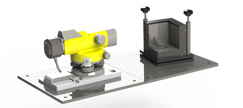
The PLX Tool Cube™ accessory is perfect for laboratory or metrology set-ups where it is necessary to establish an optical X, Y, Z coordinate system. It presents three mirror surfaces that are at near perfect right angles to each other.
The tool cube, used in conjunction with an autocollimator, is also useful in verifying the accuracy of optical devices that deviate a beam by 90 degrees. These include Penta-Mirrors, Penta Prisms, Right Angle Prisms and Roof Prisms.

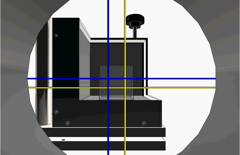
The autocollimator views the back panel and also the bottom panel via the prism. The tilt measured by the autocollimator is an indication of the accuracy of the prism.
The tool cube can also be used to verify the accuracy of angle blocks and other mechanical tooling with the use of a front surfaced mirror and an autocollimator.
The autocollimator would look at the front surface mirror and the tool cube panel behind it and compare the relative tilt to determine the sqareness of the device.

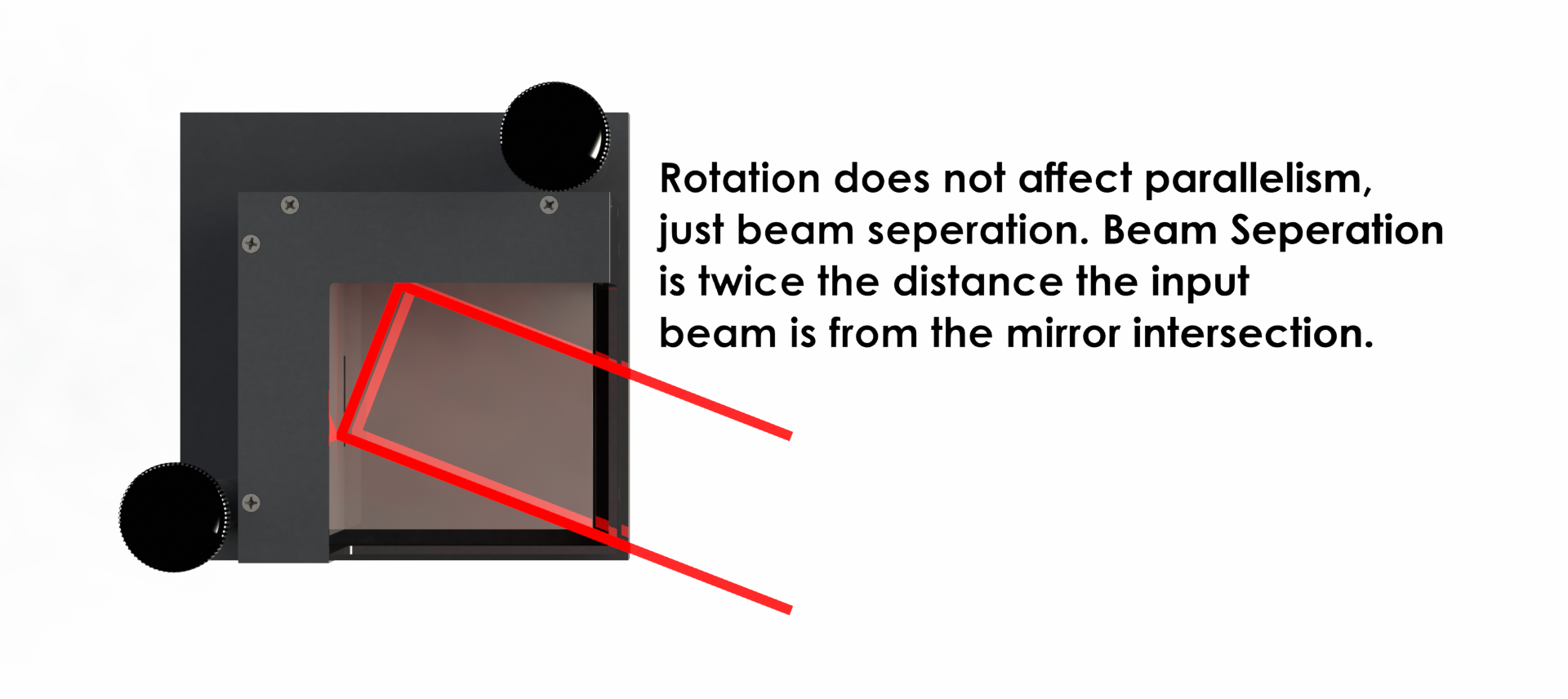
Another function of the tool cube is for setting up a second optical axis parallel to the first axis.

